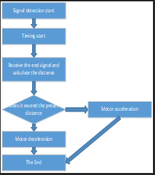
Figure 1: Flight altitude program flow chart.
RESEARCH ARTICLE
Abstract • The system uses TM4C123G as the core of quadrotor autonomous vehicle control, which consists of flight control module, power supply module, motor speed control module, optical flow sensing module, and target tracking identification module. The flight control module includes angle sensor, gyroscope, and TLS1401-LF module. The flight control processes the collected data through the chip (TM4C123G), and processes the data with PID control algorithm, while solving the PWM increment and decrement needed for the corresponding motor, adjusting the motor in time and adjusting the flight attitude. The binocular camera identifies the color of the pole tower and measures the distance, so that the distance between the aircraft and the nearest point of the pole tower is kept within 50±10cm. After detecting the red (green) tower as the center, fly around the tower clockwise (counter) for one week (top view). Finally, the OV7725 camera is used to identify the solid black circle mark of the landing point and land smoothly and accurately in the target area, thus realizing an efficient robot around the barrier.
The system mainly consists of flight control module, optical flow sensing module, attitude detection module, motor speed control module, image processing and computing module, and target tracking and identification module, and the selection of these modules are discussed below.
Solution 1: The TSL14010L's linear sensor array consists of a 128x1 array of photodiodes. The operation simplifies the internal control logic and requires only one serial input (SI) for the signal and clock. It has the advantages of simpler operation, less data, and low processing difficulty.
Solution 2: 0V7725 is a CMOS camera device, is a color CMOS type image acquisition integrated chip, providing high performance in a single small package, the device resolution can reach 640X480, the transmission rate can reach 30 fps. 5V power supply, power consumption <120mW at work, standby power <10uW.
In a comprehensive comparison, OV7725 is able to identify more site information with abundant microcontroller resources.
Solution 1: Using serial reading mode MPU6050 (JY-61), the module internal integrated attitude solver, with dynamic Kalman filter algorithm, can accurately output the current attitude of the module in a dynamic environment, attitude measurement accuracy of 0.01 degrees, and the use of high-precision gyro accelerometer MPU6050, very high stability.
Solution 2: using 12C read mode four-axis flight control sensor module GY-86, module 12C bus mounted MPU6050 + HMC58831 + MS5611, can measure the three-axis acceleration, three-axis angular velocity, three-axis magnetic field and air pressure.
In a comprehensive comparison, the GY-86 is more suitable for attitude control of quadrotor during motion.
Solution 1: OV7725 range finding, relatively lightweight, open source, easy to use, low power consumption.
Solution 2: HBV-1780 binocular ranging. This method is currently generally used for high precision measurement at close range. The same object obtained from two cameras, based on parallax to measure the distance, but requires high arithmetic power to achieve.
In a comprehensive comparison, the OV7725 is more suitable for target tracking identification during the flight around the pole.
The flight altitude is collected using the optical flow sensor module to achieve, through the optical flow when issued to start timing, stop timing when the return signal is received, the microcontroller uses the mathematical relationship between the speed of sound propagation in the air and time to calculate the time of the aircraft from the ground, so as to control the flight altitude of the aircraft to reach our desired height. The program flow is shown in Figure 1.
Figure 1: Flight altitude program flow chart.
The three degrees of freedom to control the attitude of the vehicle, the attitude deviation derived from the given attitude and attitude detection algorithm as input, the input quantity of the controlled object model as output (e.g. attitude increment), so as to achieve the role of controlling the attitude of the vehicle, the most commonly used is PID control and its various PID extensions (segmentation, fuzzy, etc.).
PID algorithm is a common algorithm in the control module of quadrotor unmanned aerial vehicle, mainly used for attitude adjustment of the vehicle, so as to achieve stable flight of the aircraft. The parameters in the PID algorithm are defined as follows.
(1) P (Proportion), is proportional. It refers to multiplying the input deviation by a constant.
(2) I (Integral). It refers to the integration operation of the input deviation.
(3) D (Derivative). It refers to the differentiation of the input deviation.
The dual closed-loop PID algorithm with angle P and angular velocity PID used in the PID algorithm. The angular error is input to the angular velocity controller as an expectation. The angular velocity inner loop occupies an extremely important position in the cascade PID algorithm. After analyzing the physical model of quadrotor flight, it is known that one of the physical manifestations causing the instability of the system is the unstable angular velocity. Therefore, if a better closed-loop control of the angular velocity of the system can be performed directly, the dynamic characteristics of the system and its stability will definitely be improved, and the angular velocity inner loop is usually referred to as the stabilization link. And the role of the angular outer loop is reflected in the precise control of the attitude angle of the quadrotor.
The designed small quadrotor is suitable for indoor low-speed flight, so the effect of air drag is ignored. Therefore, the simplified dynamic model of the vehicle is
There is a solid black circle mark at the landing point, so we place the OV7725 camera at the bottom of the aircraft, the camera identifies the circle and then transmits the location of the center of the circle to the microcontroller in a high and low level way, the microcontroller reacts to the signal and controls the ESC, so as to achieve the recognition of the landing effect and thus control the flight trajectory of the UAV. The flow chart of the program is shown in Figure 2.
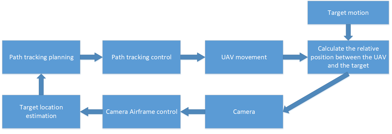
Figure 2: Flow chart of the procedure.
The overall system block diagram is shown in Figure 3.
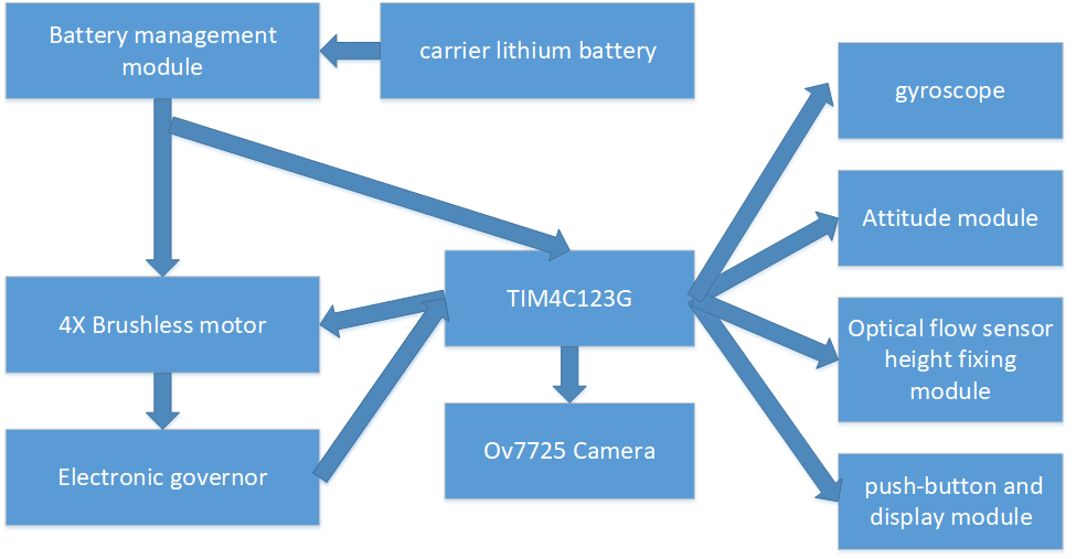
Figure 3: Overall system block diagram.
The block diagram of the height demonstration subsystem is shown in Figure 4.
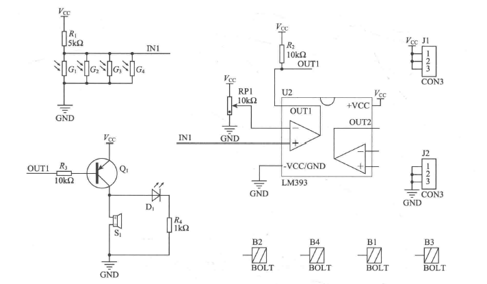
Figure 4: Block diagram of the height demonstration subsystem.
The main program flow chart is shown Figure 5.
①Wiggle the gyroscope to judge whether the PID program control is correct according to the PWM duty cycle returned by the oscilloscope.
② Shake the gyroscope. Adjust the parameters of MPU 6050 according to the data displayed on the liquid screen. Convert the returned data into the required number of PID after doing calculation.
③ Simulation of the pitch angle, set the initial pitch angle to 20 degrees, the desired angle is 0 degrees, and use the designed attitude control loop to control it under the condition of ignoring the external
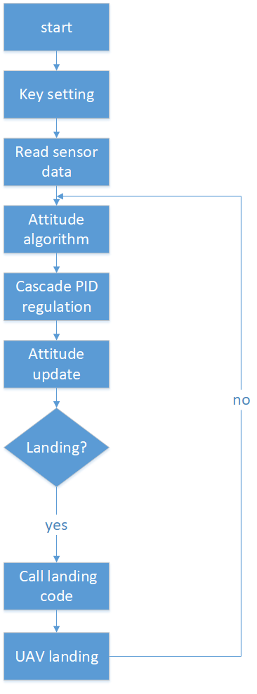
Figure 5: Main program flow chart.
disturbance.
2) Hardware testing
① Use the optical flow sensor to set the altitude and use the remote control to control the heading to make sure it can maintain a certain altitude.
② Write the camera code to make sure the frame rate is sufficient and the graphics can be judged correctly.
③ Use the camera to control the flight direction, and complete the design requirements.
Cruise flight into the defense zone. After the landing action, the aircraft will slightly deviate from the starting point, the height of the body will remain unchanged, hover for 2 seconds, and will move somewhat within the same height, the color of the tower A will be recognized by the camera and the distance will be measured, the distance between the aircraft and the nearest point of the tower will be kept within 50±10cm. After the red tower is detected, it will fly around the tower clockwise for one week (top view); after the green tower is detected, it will fly around the tower counterclockwise for one week (top view). Finally, the OV7725 camera is used to identify the solid black circle mark of the landing point and land smoothly and accurately in the target area.
Check several times, the simulation circuit and hardware circuit must be approximately the same as the system schematic and checked for errors, and the hardware circuit is guaranteed to be free of dummy solder.
The basic partial index measurement data is summarized in Table 1.
Table 1. Basic partial index measurement data.
|
Items |
Laser pointer trajectory and tower pole safety distance range |
Take-off to landing time |
Response when a tower pole is found |
|||
|
Times |
Inside or outside the safety range |
Success or failure |
Total time /s |
Success or failure |
Response Status |
Success or failure |
|
1 |
Inside |
Success |
110 |
Success |
Yes |
Success |
|
2 |
Outside |
Failure |
103 |
Success |
Yes |
Success |
|
3 |
Inside |
Success |
112 |
Failure |
Yes |
Success |
The indicator measurement data is summarized in Table 2.
Table 2. Indicator measurement data.
|
Items |
Color detection |
Landing point identification |
||
|
Times |
Detection results |
Success or failure |
Identification results |
Success or failure |
|
1 |
Yes |
Success |
No |
Failure |
|
2 |
Yes |
Success |
Yes |
Success |
|
3 |
No |
Failure |
Yes |
Success |
Although the stability of the vehicle meets expectations, there is still a lot of room for improvement in terms of anti-interference, and we hope to find a new balance in terms of stability.
The research is financed by National Undergraduate Innovation Project (No.202110856009) and Shanghai University Student Innovation Project (No.cs2102010).
[1] C. Zhao, Y. Liu, L. Chen, F. Li, and Y. Man. "Status and Prospects of Multi-UAV Path Planning with Meta-Heuristic Oriented Algorithms." Control and Decision. 2021: doi: 10. 13195/j.kzyjc.2021.1210.
[2] Y. Zhang." Automatic UAV flight path planning method based on Bayesian decision making." Computer Measurement and Control, 2021.
[3] W. Wang, H. Z. Huang, and R. Z. Li. "Indoor autonomous obstacle avoidance for UAVs based on improved artificial potential field method." Electronic Design Engineering, 2021, 29(18):95-98.
[4] N. Wang, J. Dai, J. Ying, Y. Li, L. Lu. "Simulation of multiple UAV trajectory planning based on adaptive extended potential field". Journal of System Simulation, 2021, 33(09):2147-2156.
[5] Y. Chen, X. Zhai, Y. Song, M. Wu, X. Zhang, and S. Cao. "UAV high-precision localization and vision auto-tracking fusion technology." Combined Machine Tools and Automated Machining Technology.2021, (09):103-106.
[6] K. Li, Y. Lu, S. Bao, and P. Xu. "UAV 3D obstacle avoidance planning based on improved RRT algorithm." Computer Simulation, 2021, 38(08):59-63+96.
[7] Y. Cheng and T. Zheng. "Deep learning for UAV binocular vision obstacle avoidance research." Electro-Optics and Control, 2021.
[8] F. Song, and X. Lu. "UAV obstacle avoidance strategy based on coordinate transformation technology." Electrical Technology, 2021, 22(07):53-59.
[9] Y. Cao. "Research and implementation of key technologies for unmanned aircraft obstacle avoidance flight system." University of Electronic Science and Technology, MA thesis, 2021.
Appendix 1. Four-axis drive control section circuit schematic.

Figure 6. Four-axis drive control section circuit schematic.
Appendix 2. Power Module Circuit

Figure 7. Power Module Circuit.