1. Design
1.1 Motion Chassis
Plan 1: Motion chassis of Ackerman steering
Steering mechanism: Four bar mechanisms and a steering gear are used to control the wheel steering ahead of the car.
Source of power: driven by a motor. The steering effect is obvious and easy to control.
Plan 2: Motion chassis in differential
Steering mechanism:Dual motor with differential and direction change.
Source of power: Dual motor. While the effect is poor. The difficulty lies in that the strength of the differential is not easy to control. Also, the car body shakes and is not easy to turn during traveling.
We finally choose Plan 1 after balancing.
1.2 Choice of Tires
Plan 1: We can choose tires with complex patterns for the convenience of climbing and parking, which improves the static friction factor.
Plan 2: We can also choose the rear tires with complex patterns while the front tires are relatively smooth. This helps to improve the steering sensitivity thus facilitating the test.
We finally choose Plan 2 after balancing.
1.3 Power-Supply Model
We choose the power module Lm2940, which transforms voltage from 7.2V to 5V. We also choose Lm1117, which transforms voltage from 7.2V to 3.3V.
Plan 1: TPS54317
TPS54317 has a programmable frequency and external compensation, which has a single output with step-down mode. Its input ranges from 3V to 6V. Its output ranges from 0.891V to 3.3V. Unfortunately, there are few made-up articles.
Plan 2: TPS63020
TPS63020 can decrease voltage to 2.5V or lower. At the same time, there are three inputs and outputs, and the converter can be disabled to minimize battery consumption. The mode can boost and depressurize, with an input voltage of 1.8 ~ 5.5V and an output voltage of 1.2 ~ 5.5V. We have more made-up articles of this type.
We finally choose Plan 2 after balancing.
1.4 Driving Model
HIP4082 and IRLR7843 are used as the main chips of the motor drive board, but only one circuit of the motor drive is used. FAULHABER 2224V009SR motor is selected as the power source of the main drive wheel. Compared with other motors, the motor has good controllability and excellent climbing performance because of its precision, small vibration, stable operation, extremely low power consumption and very high torque, about 1.5 .
1.5 Sensor
Plan 1: Grayscale Sensor
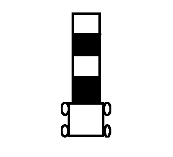
The detection distance is small and the reflectivity is different, so the module can be used for tracking. It is simple and easy to handle, getting logical values. The sample is shown below[1]:
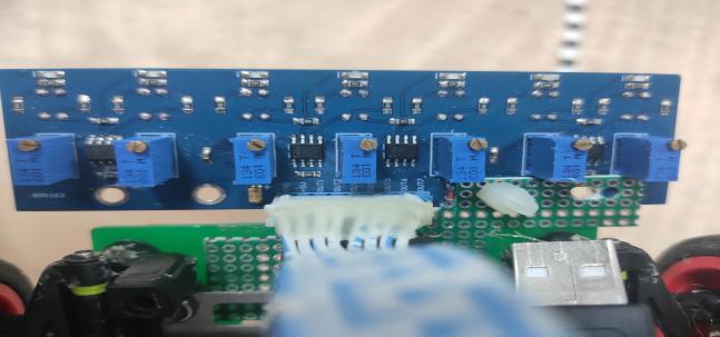
Figure 1 Installation of Greyscale Sensor
Plan 2: CCD Camera
It can sample to process black-and-white images to obtain the deviation value of the black-and-white edge. Thus, we can obtain the angle value of direction. MSP430 is not easy to process images and needs to invest in a long time.
We finally choose a grayscale sensor after balancing.
1.6 Overall Designing of the System
Overall, MSP430F5529 is used as the main control, and the motor drives the car forward[2]. After judging the logic according to the return value of the seven gray sensors placed in the front of the car, the direction deviation is calculated according to the weight algorithm of the distance between the sensors in the middle, and the duty cycle of the car steering gear is controlled by the single-chip microcomputer to realize the line patrol of the car. The speed closed loop is completed by reading the encoder to set the time to complete the task.

Figure 2 Track of the Task
Here comes an overview of this task:
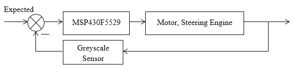
Figure 3. Overall design of our thought
2. Power Analysis of Hardware
TPS61088 is a fully integrated boost converter with high power density, equipped with a power switch and a rectifier switch. It has a switching current capacity and can provide an output voltage up to , which is enough to drive the FAULHABER motor on the trolley and provide an effective torque guarantee.
3. Designing of Circuit and Program
3.1 Circuit
3.1.1 The Circuit of Driving Model
We adopt the HIP4082 model and IRLR7843 chip, whose circuits are displayed below[3]:
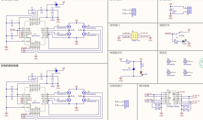
Picture 4 The Circuit of driving model
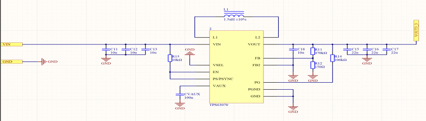
3.1.2 DC-DC Circuit of Boosting Model
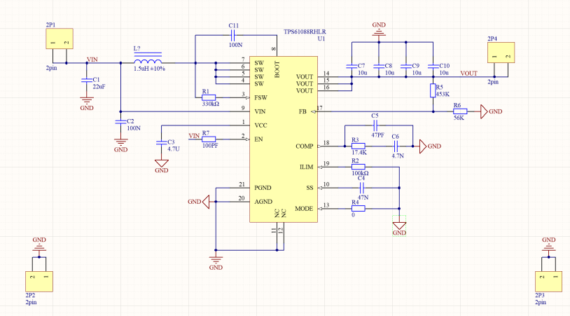
Picture 5 DC-DC Circuit of boosting model
3.1.3 DC-DC Circuit of Step-down Model
Picture 6 DC-DC Circuit of step-down model
3.2 Program
3.2.1 Designing of the Program
The logic judgment is carried out by collecting the digital signal returned by the grayscale sensor. The deviation is obtained by weight comparison, and the corresponding PWM wave is output to control the steering gear; the motor speed closed loop is completed by reading the encoder[4][5].
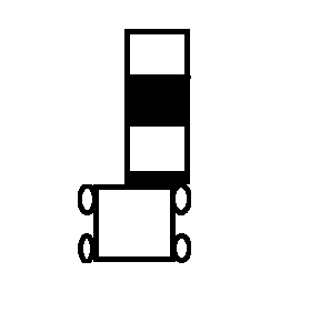
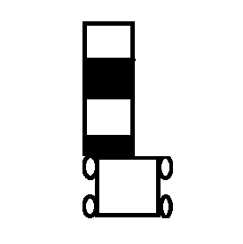
Picture 7,8,9 Deviation of the car
3.2.2 Incremental PID Algorithm
The motor drive adopts an incremental PID algorithm. The proportional link makes a rapid response, and the integral link realizes no static error, then the differential link reduces overshoot and speeds up dynamic response. Thus, the system has good performance, can well offset in the specified direction, and has good stability. Through a large number of debugging PID parameters, the game tasks such as trajectory, path motion and static balance can be realized finally.
4. Testing and Results
4.1 Plans of Testing
After completing its structure construction, drawing each part of the circuit and welding circuit, we tested whether each circuit can work normally. After the program is written and run, the detection device can realize the functions of each part. For example, whether the car can patrol the line, stop at the termination point.
4.2 Testing Instruments
Power supply, Panel of the track, Oscilloscope Multimeter.
4.3 Testing Results
The measured data are shown in the table below.
Table 1 Results of its Basic Tasks
|
Index Times |
Running Time (Seconds) |
Gradient(degree) |
Assess |
|
1 |
9.8 |
0 |
Good |
|
2 |
13.5 |
15 |
Good |
|
3 |
15.9 |
20 |
Good |
|
4 |
19.8 |
25 |
Good |
|
5 |
23.9 |
30 |
Good |
|
6 |
/ |
35 |
Failed |
|
7 |
/ |
40 |
Failed |
Table 2 Stability of Each Test
|
Index Times |
Gradient(degree) |
Assess |
|
1 |
0 |
Stable |
|
2 |
15 |
Stable |
|
3 |
20 |
Go beyond the terminal mark |
|
4 |
25 |
Go beyond the terminal mark |
|
5 |
30 |
Deviate from due track |
|
6 |
35 |
Failed |
|
7 |
40 |
Failed |
The Closed Loop of Speed is completed by reading the encoder so that the time to complete the task can be set.
According to the weight algorithm of the distance between the grayscale sensors in the middle, the direction deviation is calculated, and the duty cycle of the car steering gear is controlled, so that the car line patrol can be better realized.
Due to shortcomings in hardware and limitation in time, we finished a made-up article in the end. While there remain several points to improve, we believe that we can do better next time.